Electromagnetic Flow Meter Selection for Conductive Liquid Service
Choosing an electromagnetic flow meter starts with the liquid and the measurement job, not with the pipe nominal size. A magmeter can measure conductive liquids without a rotor or other moving part in the flow path, but it still needs a full pipe, compatible wetted materials, a suitable flow range, and a sound electrical installation.
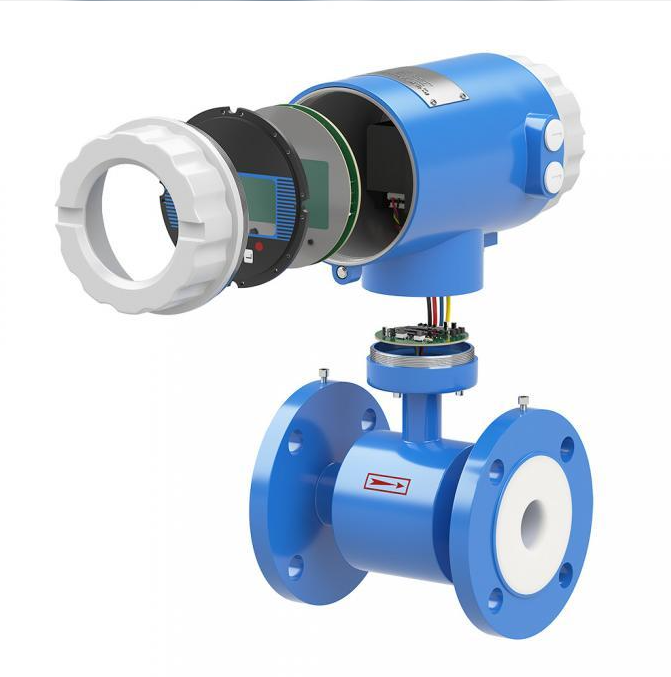
Choosing an electromagnetic flow meter starts with the liquid and the measurement job, not with the pipe nominal size. A magmeter can measure conductive liquids without a rotor or other moving part in the flow path, but it still needs a full pipe, compatible wetted materials, a suitable flow range, and a sound electrical installation. Get those conditions right and it can provide useful flow and total readings for water, wastewater, slurry, or process chemicals. Miss one and a technically capable meter may give unstable readings or fail to answer the process question.
Contents
1. Start with the liquid and measurement purpose
2. Size the meter from the real flow range
3. Published data for the ASATN meter
4. Choose liner and electrodes for the chemistry
5. Plan installation and signal integration
6. A real wastewater measurement example
7. Information to include in an RFQ
8. Frequently asked questions
9. Conclusion
Start with the liquid and measurement purpose
An electromagnetic flow meter works through Faraday’s law of induction: conductive liquid moving through a magnetic field generates a voltage that the meter converts into a flow signal. The principle suits many water-based liquids, including wastewater and some slurries. It does not make the instrument universal. ISO 20456:2017 applies to industrial electromagnetic flowmeters measuring conductive liquid in a closed conduit running full; it excludes partially filled pipes and open channels. The standard’s current status was confirmed by ISO in 2023.[2]
Before comparing models, define what the reading will control or verify. Is it a pump discharge, a treatment-stage balance, a batch total, or a transfer quantity used for invoicing? Then record the liquid’s composition, conductivity if known, temperature, pressure, suspended solids, cleaning chemicals, and whether flow can reverse. These details affect the sensor size, lining, electrode alloy, mounting style, and transmitter outputs.
Size the meter from the real flow range
A common buying shortcut is to specify the same nominal diameter as the pipeline. That can be right, but it is not proof of a good selection. The operating flow rate determines velocity through the meter. The ASATN product page lists a velocity range of 0.01 to 10 m/s, with custom ranges subject to review.[1] A project should check the normal, minimum, and maximum flow against the proposed bore, not just the design point.
For a full circular pipe, the first-pass relationship is Q = v × A. As a transparent sizing illustration, assume an actual internal diameter of 100 mm and a velocity of 1.0 m/s. The cross-sectional area is about 0.00785 m², so the calculated flow is approximately 28.3 m³/h. This is a geometric calculation, not a guaranteed operating point or a recommendation to buy DN100. The real internal diameter, flow profile, and meter-specific sizing limits must be confirmed.
Published field | ASATN product page | Buyer verification |
Bore | DN15–DN3000 | Confirm exact sensor size and connection standard |
Velocity range | 0.01–10 m/s; custom ranges listed | Check minimum, normal, peak and reverse flow |
Accuracy | ±0.5% stated | Request the applicable accuracy conditions and calibration record |
Outputs | 4–20 mA; RS485 and HART options listed | Confirm signal protocol, power, wiring and PLC/DCS mapping |
Protection and construction | IP65/IP68; integral or remote options | Confirm enclosure rating for the actual installation location |
Wetted parts | Rubber, PTFE or polyurethane liners; 316L, tantalum or Hastelloy electrodes listed | Approve material compatibility against the liquid and cleaning regime |
These are published product-page values, not universal performance guarantees. Accuracy depends on the selected model and specified operating conditions. Ask the supplier to state the conditions associated with its quoted figure, including the flow range and calibration method.
Choose liner and electrodes for the chemistry
The liner separates the process liquid from the meter body, while the electrodes contact the liquid to sense the induced voltage. Selection should follow actual chemistry and temperature, not a broad label such as “corrosive.” A dilute acid, alkaline wash, salt solution, and abrasive slurry impose different demands. The materials listed by ASATN include rubber, PTFE, and polyurethane liners and 316L, tantalum, and Hastelloy electrodes.[1] That list is a starting point. It does not establish chemical suitability for every concentration or temperature.
Send a current chemical composition or safety data sheet when possible. Include concentration ranges, cleaning-in-place chemicals, solids, and any expected changes in the recipe. If conductivity is unknown, ask whether a sample test or measured value is needed. The public product page does not state a minimum conductivity or a universal pressure and temperature envelope, so those limits should be confirmed for the exact configuration rather than inferred.
Plan installation and signal integration
The sensor should remain full during measurement. Horizontal installation is common, but the electrode orientation, nearby valves, pump discharge, elbows, reducers, and the risk of air pockets all matter. Follow the specific meter manual for straight-run requirements. Do not assume that one installation rule applies to every meter; special designs can tolerate tighter layouts, while ordinary designs may need more developed flow upstream.
Grounding and bonding need equal attention. The liquid is part of the measurement circuit, so the installation must provide the grounding arrangement required for the pipe material and sensor design. Confirm whether grounding rings are needed for lined or nonconductive pipe. Before ordering, verify flange standard, face-to-face length, pressure class, transmitter location, cable length for remote mounting, power supply, output type, and the destination of the totalizer value.
A real wastewater measurement example
The City of Pendleton wastewater treatment facility in Oregon had been estimating process-water flow because its previous arrangement could not provide a usable measurement. The pipe layout was difficult: flow rose vertically through a 90-degree elbow and joined a full-port valve, leaving little straight pipe. The facility adopted a full-bore electromagnetic meter designed for unrestricted mounting. The reported result was repeatable flow and total readings; the lead technician said the new data helped the crew identify and correct two issues.[3]
This is a documented case from another supplier, not an ASATN installation or a promise of the same result. Its useful lesson is narrower: when pipe layout is constrained, capture the geometry early and confirm that the exact meter has been designed and approved for it. A standard meter should not be assumed to inherit the installation tolerance of a specialized model.
Information to include in an RFQ
RFQ item | What to provide | Why it matters |
Process liquid | Name, concentration, conductivity if known, solids and cleaning chemicals | Supports electrode and liner review |
Flow envelope | Minimum, normal, maximum and reverse flow | Checks velocity and range coverage |
Pipeline | Actual internal diameter, material, pressure class and flange standard | Confirms fit and grounding approach |
Operating conditions | Temperature, pressure, ambient exposure and flooding risk | Defines sensor, transmitter and enclosure requirements |
Controls | Power, 4–20 mA / RS485 / HART needs, PLC/DCS and totalizer use | Avoids signal or integration mismatch |
Documentation | Calibration record, material declaration, wiring and installation manual | Makes acceptance and maintenance traceable |
Frequently asked questions
Can an electromagnetic flow meter measure clean water?
Yes, if the water conductivity meets the meter’s stated limit and the pipe remains full. Ask the supplier for its minimum conductivity value because it is not stated on the public ASATN product page.
Can it measure slurry or wastewater?
Many conductive slurries and wastewater flows are suitable, but suspended solids, chemical composition, liner abrasion, and electrode fouling should be reviewed for the specific service.
Does the meter need a straight pipe run?
That depends on the sensor design and installation. Follow the exact manual and provide upstream and downstream geometry in the RFQ. The City of Pendleton case involved a special unrestricted-mounting design, not a universal exemption.
What should be checked before shipment?
Verify the approved data sheet, bore, flange, lining, electrodes, transmitter arrangement, output protocol, calibration evidence, and the process conditions used for that evidence.
Conclusion
An electromagnetic flow meter is a sound choice when the liquid is conductive and the pipe runs full, but selection still depends on the duty envelope and the installed system. Use actual flow data to size the bore, confirm the wetted materials against the chemistry, and treat installation and signal integration as part of the measurement design. ASATN’s published page gives buyers a useful starting specification; the final quote should resolve the application limits that are not listed publicly.