Electromagnetic Flow Meter Selection for Conductive Liquids and Slurries
An Electromagnetic Flow Meter can be remarkably dependable when the liquid, pipe, lining, electrodes, grounding, and installation conditions are treated as one measurement system. It can also disappoint when buyers select it by pipe diameter alone.
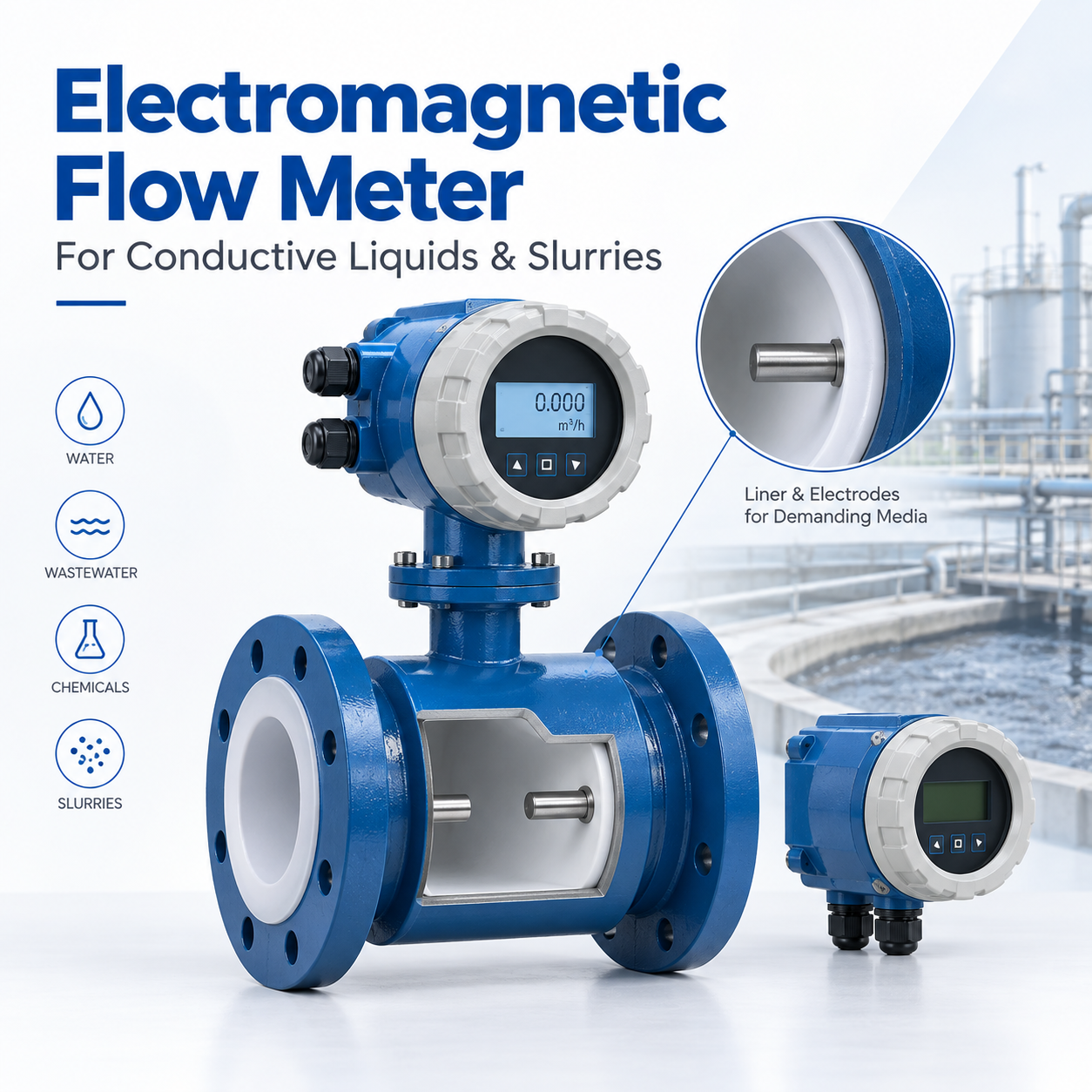
An Electromagnetic Flow Meter can be remarkably dependable when the liquid, pipe, lining, electrodes, grounding, and installation conditions are treated as one measurement system. It can also disappoint when buyers select it by pipe diameter alone. A nominal DN size tells us whether the body fits the line; it does not tell us whether the fluid is conductive enough, whether solids will abrade the lining, or whether the pipe will remain full at low demand.
At AnSanAn, we begin with the process rather than the catalogue code. That means reviewing the fluid, operating flow range, temperature, pressure, pipe material, chemical compatibility, available straight run, power supply, signal requirements, and maintenance access. This approach takes a little more work at the specification stage, but it prevents far more expensive corrections after installation.
Table of Contents
1. How an Electromagnetic Flow Meter Measures Flow
2. Start with the Fluid, Not the Flange Size
3. Size the Meter for Velocity and Turndown
4. Installation Details That Protect Accuracy
5. Signals, Diagnostics, and Control Integration
6. Calibration and Acceptance Before Shipment
7. Frequently Asked Questions
8. Specify the Meter Around the Real Process
How an Electromagnetic Flow Meter Measures Flow
The operating principle comes from Faraday's law of electromagnetic induction. Field coils create a magnetic field across the measuring tube. As a conductive liquid moves through that field, it generates a voltage between two electrodes. The voltage is proportional to average liquid velocity. The transmitter processes that signal and combines it with the known tube area to calculate volumetric flow.
This principle brings several practical advantages. There is no turbine, paddle, or obstruction in the measuring tube, so the meter creates little additional pressure loss. The open bore is useful for water, wastewater, chemical solutions, and many slurries that would quickly trouble a small mechanical passage. Measurement is based on velocity rather than density, viscosity, or pressure drop, although extreme process conditions can still affect signal quality and material life.
There are firm application boundaries. The liquid must be conductive, and the measuring tube must remain full. Hydrocarbons, many solvents, gases, and steam are normally outside the useful range of magnetic flow measurement. Very low conductivity, entrained gas, empty-pipe conditions, heavy coating, or poor grounding can create an unstable zero or noisy output. That is why a sound specification starts with the medium and operating envelope, not with a broad statement such as “for liquid service.”
Start with the Fluid, Not the Flange Size
The same pipe can carry clean water one year and an aggressive dosing solution the next. Those two duties may need different liners and electrode materials even if flow and pressure are identical. We therefore ask buyers to identify the actual chemical composition, concentration, temperature, suspended solids, cleaning method, and any expected process variation.
Conductivity and Process Stability
Conductivity must stay above the meter's stated minimum under real operating conditions. A fluid can become less conductive when concentration or temperature changes, so a single laboratory value may not describe the whole process. Where the application is near the lower limit, we review the minimum expected conductivity and the length and shielding of remote signal cables. A stable conductive path, correct grounding, and suitable cable routing matter more than an impressive display resolution.
The pipe should also stay completely full at the sensor. A partially filled horizontal line may expose the upper electrode and produce erratic readings. A vertical installation with upward flow is often useful where the liquid contains solids or bubbles because it helps keep the tube full and discourages deposits. The final arrangement still depends on access, pressure, drainability, and the equipment around the meter.
Liner and Electrode Compatibility
The liner electrically isolates the process liquid from the meter body and protects the tube from corrosion or abrasion. Electrodes contact the liquid and must resist the same chemistry. Neither item should be chosen by habit. PTFE-based liners are widely considered for corrosive liquids and higher temperatures, while rubber-type liners are often attractive for water or abrasive service. Actual limits depend on the detailed construction and must be confirmed for the selected model.
Electrode selection follows a similar logic. Stainless steel may suit many water duties, while more resistant alloys are considered for aggressive chemicals. A premium alloy is not automatically the best answer: the complete chemical environment, concentration, temperature, cleaning agent, and expected service life should justify it.
Process condition | Liner direction to evaluate | Electrode direction to evaluate | Main purchasing question |
Clean or treated water | Rubber or PTFE family, subject to pressure and temperature | Stainless steel may be suitable | Will the tube remain full across the entire flow range? |
Wastewater with suspended solids | Abrasion-resistant rubber or suitable polymer | Corrosion-resistant material matched to chemistry | Are solids abrasive, fibrous, or likely to coat the electrodes? |
Acid or alkali solution | Chemically resistant fluoropolymer | Alloy selected from a compatibility review | What are concentration, maximum temperature, and cleaning chemicals? |
Mineral or process slurry | Abrasion-resistant liner selected for solids loading | Material that tolerates both wear and corrosion | What are particle size, solids percentage, and normal velocity? |
Hygienic conductive liquid | Compatible smooth lining and process connection | Material accepted by the process specification | How will the meter be cleaned and drained? |
This table is a starting point, not a material guarantee. Compatibility must be checked against the precise medium and operating limits. Small changes in concentration or temperature can alter the choice.
Size the Meter for Velocity and Turndown
Matching the meter bore to the existing pipe is convenient, but it can leave the instrument operating at an unsuitable velocity. An oversized sensor may produce weak resolution at minimum flow and allow solids to settle. An undersized sensor raises velocity and may increase wear or introduce avoidable pumping demand through reducers and adjacent piping.
We prefer to calculate velocity at minimum, normal, and maximum flow, then select the measuring diameter around the useful operating window. Where the sensor is smaller than the process pipe, gradual reducers can be used if the hydraulic and pressure requirements allow. The transmitter's stated turndown should not be confused with good process design; a meter may generate a number at very low velocity while the installation still lacks the stability needed for control or accounting.
For batching and dosing, response time and totalizer behavior deserve attention. For network monitoring, low-flow repeatability and data communication may matter more. For slurry transfer, maintaining a velocity that limits settling without causing excessive abrasion can dominate the decision. The best size is therefore an application choice rather than a flange-matching exercise.
Installation Details That Protect Accuracy
An Electromagnetic Flow Meter does not require a perfectly developed laboratory profile in every application, but disturbed flow can still shift performance. Elbows, pumps, partially opened valves, tees, and reducers create swirl or asymmetry. We review upstream and downstream fittings against the installation instructions for the chosen design instead of applying one universal straight-pipe rule.
A Utah State University investigation by B. C. Clawson tested magnetic flow meters from several manufacturers under different upstream straight-pipe lengths. The work found that meter response depended on both the disturbance and the individual meter design. The practical lesson is straightforward: straight-run recommendations are part of the measurement specification, not optional space that can be removed late in piping design. The independent study can be consulted through the Utah State University repository.
Grounding is equally important. The liquid must have a stable electrical reference, particularly in plastic or lined pipes. Depending on the piping material and meter construction, grounding rings or electrodes may be required. Signal and power cables should follow the manufacturer's separation and shielding instructions, and variable-frequency drives or large motors should be considered during cable routing.
The sensor location should avoid a pipe high point where air can collect and a downward discharge that can empty the tube. Control valves are commonly better placed downstream so the meter remains under positive pressure. Pumps should not draw directly through an arrangement that encourages vacuum or cavitation. The transmitter display must be accessible, yet the enclosure and cable entries still need protection from washdown, weather, flooding, and condensation.
A Practical Installation Review
Before releasing a drawing, we check five items together:
· the pipe stays full during start-up, normal operation, and shutdown;
· electrode orientation reduces exposure to air pockets and settled solids;
· nearby fittings satisfy the selected model's straight-run guidance;
· grounding and cable routing suit conductive or nonconductive piping;
· valves, pumps, drains, and access space support safe maintenance.
That review often catches more risk than another decimal place on a datasheet.
Signals, Diagnostics, and Control Integration
The output package should match the control task. A 4–20 mA signal remains useful for continuous flow, while pulse or frequency output is commonly selected for totalization. Digital communication can provide configuration, status, and diagnostic information, but the protocol has to match the plant's control architecture. At AnSanAn, we support application-specific communication and interface discussions as part of OEM and ODM configuration.
Buyers should define fail-safe behavior as well as normal output. What should the controller see during an empty pipe, coil fault, electrode alarm, or loss of power? Should the totalizer retain its value? Does a remote transmitter require special cable length or cable type? Is local indication needed at the pipe, or will operators work from a control room? These questions turn an instrument purchase into an operable loop.
Diagnostics are useful only when the maintenance team knows how to interpret them. Empty-pipe detection does not repair poor piping. Electrode or grounding alarms do not replace inspection. We recommend including alarm meanings, configuration records, wiring, scaling, and commissioning values in the handover package.
Calibration and Acceptance Before Shipment
Calibration establishes how the meter indicates flow under controlled conditions. It does not make every field installation ideal, yet it gives the project a traceable baseline. The current ISO 20456 standard applies to industrial electromagnetic flowmeters used for conductive liquid in a full closed conduit and covers AC- and pulsed-DC field systems. For water-meter applications, the OIML R 49 framework also addresses test conditions such as orientation, water conductivity, straight pipe, and electromagnetic environment.
At our manufacturing base in Jinhu, liquid-flow calibration equipment supports instrument verification before shipment. We calibrate and inspect each instrument under our ISO 9001 quality system, with records tied to the configured unit. Project acceptance can also include tag checks, signal simulation, display and totalizer checks, and confirmation of the ordered process connection, lining, electrode, enclosure, power, and communication settings.
For demanding projects, the buyer should define acceptance criteria in the purchase specification: calibration points, direction of flow, allowed error, report content, tag format, units, output scaling, and any witness requirement. A clear inspection and test plan saves argument at final acceptance.
Frequently Asked Questions
Can an electromagnetic meter measure oil, gas, or steam?
Generally no. The method needs a conductive liquid moving through a magnetic field. Most oils and solvents have insufficient conductivity, while gas and steam do not maintain the required conductive liquid path. A turbine, Coriolis, vortex, ultrasonic, or differential-pressure technology may be more suitable after the process is reviewed.
Does the meter need a full pipe?
Yes. The electrodes and measuring section must remain filled with conductive liquid. A partially filled tube can create unstable or false readings. Sensor location, pipe orientation, downstream valve position, and operating pressure should be planned to maintain a full bore.
How do we select the correct liner and electrodes?
Provide the full chemical composition, concentration, temperature range, pressure, solids content, particle characteristics, and cleaning method. We use that information to review corrosion, permeation, abrasion, and temperature limits rather than selecting materials from the product name alone.
Is factory calibration enough for every project?
Factory calibration provides a controlled performance baseline. Field accuracy still depends on correct sizing, full-pipe conditions, grounding, wiring, configuration, and hydraulic installation. Regulated or high-value measurement points may also require site verification or periodic recalibration under the owner's quality plan.
Specify the Meter Around the Real Process
A reliable Electromagnetic Flow Meter begins with an honest process description: what the liquid is, how the flow changes, what the pipe looks like, where disturbances sit, and how the signal will be used. Send AnSanAn the medium data, flow range, pipe details, operating conditions, connection standard, and control requirements. We can review the measurement point and prepare a configuration that is ready for technical approval rather than leaving key choices to installation day.